
Top Flange Penstock Gate Essentials and Practical Applications
2026-07-18
When it comes to controlling high-pressure water flow in hydro plants, irrigation systems, or dam outlets, the top flange penstock gate often flies under the radar—until it doesn’t. These robust valves are mission-critical, yet their design nuances and field applications are rarely discussed in plain terms. At THT, we’ve seen firsthand how a well-chosen gate can slash downtime and maintenance headaches. In this post, we’ll strip away the jargon and get into the essentials that every engineer and project manager should know, plus real-world scenarios where the right penstock gate makes all the difference. Ready to rethink what you know about flow control?
Key Components That Make a Top Flange Gate Work
Understanding the inner workings of a top flange gate begins with its seal geometry and closure mechanism. Unlike standard gates that rely solely on wedge action, this design often incorporates an elastomer-encapsulated wedge disc that flexes slightly under pressure to maintain a tight shutoff. The top flange mounting point isn't just a connection—it's a reinforced hub that aligns the stem bushing and thrust bearing, ensuring linear motion without binding even after years of cycling. That subtle combination of flexible disc sealing and precise stem guidance is what transforms a basic gate into a reliable isolation point in critical low-pressure systems.
The bonnet assembly plays a dual role that's easy to overlook. It houses the stem seal—usually a set of adjustable packing rings compressed by a gland follower—while also providing the rigid top flange interface. When you torque down the actuator or handwheel onto that flange, the entire load path transfers through the bonnet, not the valve body, which prevents stress distortion around the seat pockets. Another component that quietly dictates performance is the non-rising stem design common in these models. The stem threads into the disc internally, so the overall height remains fixed, making it ideal for cramped installations while protecting the threads from external debris.
Don't underestimate the wear rings and side guides tucked inside the body. These components absorb the differential pressure thrust when the gate is partially open, stopping the disc from chattering against the seats. In top flange configurations, the guides are often machined directly into the body or fitted as replaceable inserts, allowing field maintenance without pulling the entire valve from the line. This modularity—separable top flange, renewable seat rings, and guided disc—means the valve doesn't just work; it keeps working through cycles that would quickly degrade a simpler design. The real key is in how these pieces interact: the top flange centerline, the stem, and the disc guides all share a common axis, eliminating side loading that causes premature packing wear and seat leakage.
How Top Flange Design Influences Flow Control
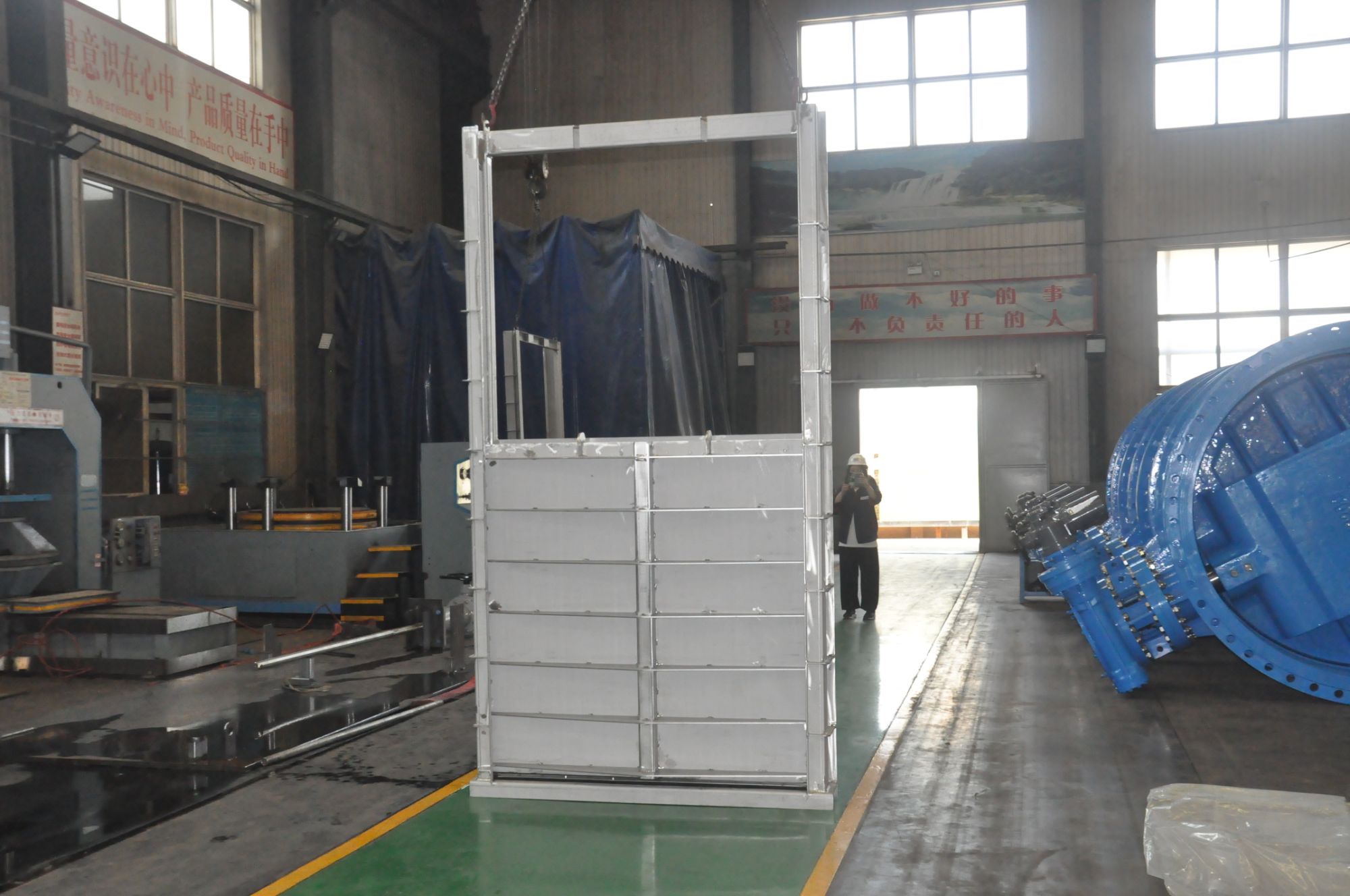
The geometry of the top flange might seem like a minor detail, but it quietly dictates how smoothly fluid or gas navigates through a system. When the flange face is precisely machined and aligned, it minimizes turbulence at connection points—those sudden disruptions that chew up energy and erode efficiency. A subtle radius or a carefully tapered transition can redirect flow seamlessly, while a poorly designed edge acts like a speed bump, scattering momentum and inviting pressure drops.
Material choice and surface finish play an unsung role too. A flange cast with a slightly textured interior might look harmless, yet it can trip the boundary layer, stirring up vortices that compound over distance. In contrast, a polished, contoured design encourages laminar flow, keeping the stream attached and predictable. Engineers often tweak these profiles iteratively, chasing that sweet spot where the flange not only seals tightly but also guides the flow with minimal resistance.
Even the bolt pattern and gasket seating can intrude on performance. An asymmetrical bolting arrangement introduces uneven compressive forces, warping the flange face just enough to skew flow paths. Gaskets that protrude into the bore, even by a fraction, become persistent sources of eddy currents. Designing the top flange isn't just about containment—it's about preserving the integrity of the flow narrative from one component to the next.
Material Choices and Their Impact on Gate Longevity
Every gate tells a story through the materials chosen for its construction, and that story often determines how many years it will stand against the elements. Wood, while classic and inviting, demands a vigilant maintenance routine—sanding, sealing, and repainting become annual rituals if you hope to keep rot and warping at bay. Steel gates bring a sense of modern strength, but their hidden vulnerability lies in the tiniest scratch that invites rust to spread beneath the surface. Even aluminum, prized for its lightness, can develop a chalky oxide layer over time that dulls its appearance and weakens its joints.
The true test of material longevity often comes down to how well it handles the less visible threats: moisture and temperature swings. Wrought iron has an almost romantic reputation for permanence, yet without hot-dip galvanizing or a zinc-rich primer, it can crumble from within as corrosion eats away at its core. Composite materials have emerged as a clever compromise, combining wood fibers and recycled polymers to mimic natural grain without the constant upkeep—though they still expand and contract in extreme heat, sometimes pulling loose from their attachments. The choice becomes less about upfront cost and more about matching the material's personality to your local climate and your tolerance for seasonal care.
Hardware matters just as much as the gate itself, because a beautiful wooden frame hung on cheap steel hinges is a failure waiting to happen. Marine-grade stainless steel brackets and fasteners can add decades to a gate's life in coastal areas where salt spray travels on the breeze. Powder-coating and e-coat treatments are the unsung protectors that shield metal components long after installation, creating barriers that touch-up paint can never replicate. Ultimately, the gates that endure aren't the ones made from a single miracle material, but those assembled with an understanding that every part—from the timber species to the hinge pin—ages at its own rhythm and needs to be chosen with that dance in mind.
Installation Insights for Long-Term Reliability
The way equipment is installed often determines how well it performs years down the line. Small oversights during setup, such as uneven mounting surfaces, improper torque on fasteners, or ignoring ambient conditions, can introduce stress points that gradually compromise structural integrity. These aren’t issues that trigger immediate failure; instead, they accumulate strain cycle by cycle, eventually leading to premature wear or unexpected downtime. A methodical approach from the very start is what separates systems that deteriorate rapidly from those that hold steady under prolonged operation.
Environmental factors at the installation site are often underestimated. A component installed in an area with excessive moisture, vibration, or temperature swings will age differently than one placed in a controlled setting. Accommodating these realities requires more than just following a generic checklist—it demands an understanding of how materials respond to their surroundings over time. Something as straightforward as allowing adequate clearance for thermal expansion or selecting appropriate fasteners for corrosive environments can significantly extend the service life of an assembly.
Long-term reliability also ties back to precise alignment and calibration during installation. Misalignment, even within tolerance limits, can impose uneven loads on bearings, seals, and mating surfaces. Over months and years, this manifests as accelerated wear, increased energy consumption, or subtle performance drift that triggers frequent adjustments. Taking the extra hours to dial in alignment and verify calibration against actual field conditions pays dividends by eliminating the root causes of many chronic maintenance issues. When installation is treated as a critical engineering phase rather than a final step, the result is equipment that continues to operate as intended without constant intervention.
Common Challenges in Maintenance and How to Tackle Them
One of the biggest headaches in maintenance is dealing with unexpected equipment breakdowns that throw production schedules into chaos. Instead of scrambling to fix things when they fail, shifting to a predictive approach can save a lot of grief. By keeping an eye on vibration, temperature, or lubrication data, you can spot trouble long before a machine grinds to a halt. It’s not about having a crystal ball—just a few well-placed sensors and a habit of checking trends can make all the difference. Once you start catching issues early, those frantic repair calls become a lot less frequent.
Wrangling a growing pile of spare parts can turn into a mess if inventory isn’t kept under control. Some items gather dust for years while critical components are suddenly nowhere to be found when you need them. The trick is to use a simple but disciplined tracking system—nothing fancy, just clear labels, minimum stock alerts, and a regular audit that catches discrepancies before they spiral. Having a clear picture of what’s on hand and what’s actually used most often means you’re not tying up cash in things that never get touched, and you’re rarely stuck waiting on a delivery.
Another common snag is a skills gap that leaves teams leaning too hard on a few experienced folks who can’t be everywhere at once. When knowledge stays locked inside someone’s head, you’re one resignation away from a real pinch. Spreading that know-how doesn’t have to mean a giant training budget—something as simple as short video clips of common fixes or a shared notebook can help. Pair that with encouraging people to swap tips during downtimes, and you gradually build a team that can handle hiccups without panicking. It makes the whole operation less vulnerable and day-to-day work a lot smoother.
Real-World Uses Across Water Management Systems
Municipal utilities rely on integrated water management platforms to track reservoir levels and anticipate demand spikes, adjusting treatment plant outputs proactively rather than reacting to shortages. In drought-prone regions, these systems draw on soil moisture sensors and weather forecasts to coordinate irrigation schedules across entire districts, prioritizing critical crops while minimizing waste. The same logic applies underground—acoustic sensors and pressure analytics feed into central dashboards that flag pipe leaks within meters of their origin, preventing water loss before it surfaces.
Flood control networks add another layer, merging river gauge data with upstream rainfall readings to issue evacuations warnings hours before water breaches predicted zones. Industrial complexes meanwhile embed closed-loop recycling within their facility designs, where process water from one operation gets treated and fed straight into another, cutting intake from municipal taps by over half without touching product quality.
FAQ
A top flange penstock gate is a closure device used in pipelines and channels to control water flow. Its defining feature is the mounting flange located at the top, which allows it to be bolted directly onto a mating surface, often on a wall or bulkhead. Unlike slide gates that rely on guides on both sides or flap gates that open with flow pressure, the top flange design provides a rigid, leak-resistant seal and is typically operated by a rising stem mechanism.
These gates primarily serve for isolation, flow regulation, and emergency shut-off in water treatment plants, reservoirs, and hydropower stations. They can stop water flow completely for maintenance downstream, modulate flow when partially opened, and act as a safety barrier in case of equipment failure or flooding.
Engineers evaluate the maximum water head pressure, seating and unseating conditions, operating environment, and the required sealing performance. The gate’s material must resist corrosion and cavitation, and the flange dimensions must match existing infrastructure. Clearances for the rising stem and actuator space above the gate are also critical.
You'll find them installed at water intake structures, wastewater treatment basins, stormwater detention facilities, and irrigation canals. They are also widely used in hydropower plants to isolate turbines from the penstock and in industrial cooling water systems where precise flow isolation is needed.
Routine inspections of seals, stem threads, and flange bolting prevent minor issues from becoming failures. Lubricating the stem and exercising the gate periodically stops seizing, while cleaning debris from the seating surfaces ensures a tight seal. Promptly replacing worn seals and repainting corroded areas protects the structure and extends operational life.
Stainless steel grades like 304 or 316 are common for the gate body and stem in corrosive or potable water applications. For larger gates or less aggressive environments, ductile iron with fusion-bonded epoxy coating offers a good balance of strength and cost. Bronze is sometimes used for seating surfaces to ensure durability and a tight seal.
Yes, they can be fitted with electric or hydraulic actuators, allowing remote operation and integration into SCADA systems. Automation enables precise positioning for flow control, reduces the need for manual effort in hard-to-reach locations, and provides instant response in emergency shutdown scenarios, improving both safety and efficiency.
Conclusion
Top flange penstock gates serve as critical flow regulators in water management systems, built around a robust frame, a vertically sliding gate leaf, and sealing mechanisms that ensure minimal leakage even under high pressure. The top flange configuration distinguishes itself by mounting actuators or stem guides above the bonnet, which not only protects the stem and drive from debris but also simplifies routine inspection. Flow control precision is largely dictated by the flange’s ability to maintain alignment under thrust loads, directly influencing how smoothly the gate travels against seating forces. When selecting a gate, engineers weigh material options carefully—stainless steel resists corrosion in harsh environments, while ductile iron offers cost-effective durability for treated water. Each choice affects gate longevity and maintenance cycles, making material matching to the operating medium a fundamental design decision.
Installation practices are equally foundational: proper grouting, squareness verification, and anchor bolt tensioning safeguard against distortion that could compromise sealing. Over time, common challenges like scale buildup, seal wear, and actuation stiffness demand a proactive maintenance approach—regular cycling, lubrication of exposed threads, and prompt replacement of worn guide strips keep the gate operational. These devices find real-world use across diverse applications, from reservoir intakes and treatment plant channels to flood control structures and irrigation networks. Their adaptability to both on-off and modulating service, combined with the accessibility provided by the top flange design, cements their role as dependable assets in civil and environmental infrastructure where reliable flow isolation directly impacts system safety and efficiency.
Contact Us
Contact Person: Su Zhang
Email: [email protected]
Tel/WhatsApp: +86-25219206
Website: https://www.tht-valve.com/