
Profile Projector Machine Manufacturer Selection Tips for Precision Quality Assurance
2026-09-28
Selecting the right profile projector machine manufacturer is more than a procurement decision—it's a direct investment in your quality assurance chain. In precision manufacturing, every micron matters, and your measurement equipment must keep pace with your tolerances. Yet with countless suppliers claiming accuracy, how do you separate genuine engineering expertise from empty promises? This guide cuts through the noise, offering practical selection criteria that put repeatability, service support, and real-world performance first. Along the way, you'll see why industry leaders like JATEN have earned their reputation—not through flashy marketing, but through machines that hold calibration shift after shift. Whether you're upgrading a QC lab or outfitting a new production line, these insights will help you choose a partner whose equipment doesn't just measure parts, but safeguards your entire quality reputation.
Verify Core Optical and Mechanical Engineering Depth
A real optical system is not just a stack of lenses on a spec sheet. The core depth shows up when someone asks about the ray fan plot, pupil aberration balance, or the tolerance stack between a 3-micron air gap and a thermal drift of 0.2 microns per degree. It means being able to walk through a design review and explain why the MTF drops at the corner of the detector, not just quote a nominal resolution. Similarly, mechanical depth isn't about naming a few mounting features—it's understanding how a kinematic mount behaves under vibration load, how a flexure design avoids parasitic motion, and how a stray light baffle actually scatters radiation into the sensor. The ability to verify this depth comes from prototypes, failure analyses, and hands-on alignment sessions that leave fingerprints on the optics.
One clear signal of genuine depth is the seamless shift between optical simulation and mechanical reality. A capable engineer uses the interferometer data to adjust the lens barrel centering, then goes back to the mechanical drawing to change a spring preload because the image plane shifted by four microns after thermal cycling. They don't treat “the optics are fine” and “the mechanics are fine” as separate statements—they chase the coupled problem. For instance, verifying core depth might involve measuring the actual radius of a diamond-turned mirror, comparing it to the design, and then re-optimizing the spacing of the secondary baffle based on the measured scatter pattern. This loop between predicted performance and measured behavior is where depth gets proven, not in a list of software tools.
Depth also shows in how someone questions a design before building it. They ask about the adhesive outgassing near the first lens, the direction of gravity during assembly, or the expected deformation of a thin-walled spacer when the retaining ring torque is applied. These are not theoretical concerns—they come from past projects where a seemingly minor mechanical choice shifted the optical axis or introduced a double image. Verifying depth means looking at a cross-section drawing and immediately noticing that the lens seat doesn't have enough fillet radius for the coating stress, or that the baffle thread pitch creates a light leak at a steep angle. That kind of instinct only develops through iterative testing, not through reading application notes.
Scrutinize Calibration Traceability and Measurement Uncertainty
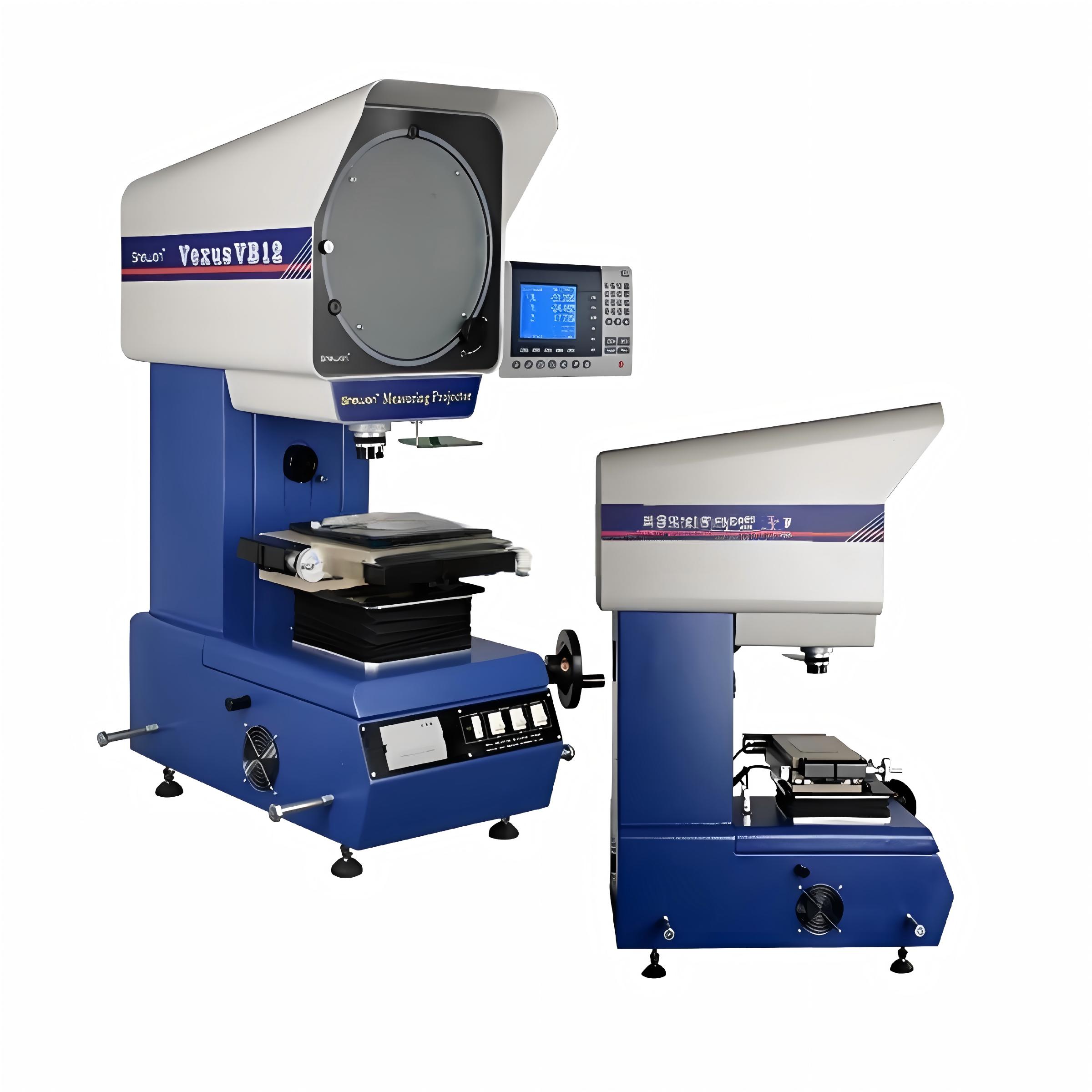
A calibration certificate is only as trustworthy as the chain of comparisons that anchors it to a recognized standard. When reviewing traceability, the immediate concern is not the headline accreditation but the granular detail—the exact reference standard used, its own calibration date, and whether any intermediate steps introduced drift or environmental bias. Laboratories often overlook the fact that traceability is not a static property; it degrades if a critical instrument sits beyond its recalibration interval or if a transfer standard is mishandled. Scrutiny here means questioning every link: who performed the last calibration, under what conditions, and with what stated uncertainties. A common failure is treating traceability as a checkbox rather than a living chain of custody that must be traceable to SI through unbroken, documented comparisons.
Measurement uncertainty is rarely given the attention it deserves, yet it dictates the real-world confidence in every reported value. When examining an uncertainty budget, the first red flag is any source term that appears suspiciously small or conveniently round. Real uncertainty seldom cooperates that way. You should also check whether the coverage factor and confidence level are clearly stated, and whether the budget includes contributions from repeatability, resolution, reference standard drift, environmental fluctuations, and operator variability. Too many reports quote a combined uncertainty that is smaller than the resolution of the instrument alone—an obvious impossibility that suggests either sloppy mathematics or wishful thinking. A rigorous review requires recalculating at least a few terms and comparing the claimed uncertainty to historical validation data or interlaboratory comparisons.
The intersection of traceability and uncertainty is where compliance often unravels. An instrument might have a beautifully documented calibration, but if the uncertainty stated by the calibrating laboratory is not propagated into downstream measurements, the final results are effectively meaningless. Conversely, a meticulously expanded uncertainty loses its value if the underlying traceability is broken by an uncalibrated intermediary device. Scrutinizing both aspects together means tracing a reported value backward through every contributing instrument and procedure, ensuring that each step carries an uncertainty that is both defensible and realistically combined. It is tedious work, but that is precisely why it gets skipped—and why failures so frequently emerge here rather than in more obvious areas.
Demand Real-World Repeatability Data, Not Just Spec Sheets
A robot arm can nail a perfect cycle time on a lab bench, yet fall apart after three hours on a dusty factory floor. Spec sheets love to tout repeatability figures measured under sterile, temperature-controlled conditions—but that tells you almost nothing about how the machine will behave when vibration, thermal drift, and unpredictable payloads enter the picture. If a vendor can't show you data from a pilot run or a customer site that mirrors your actual environment, treat their ±0.02 mm claim as little more than marketing poetry.
Push for repeatability tests that run for days, not minutes. Ask for histograms of positioning error over a full shift, not just a single averaged value. Demand to see how the system holds tolerance after tool changes, after maintenance cycles, or when the ambient temperature swings from morning to afternoon. Real-world repeatability is messy and distribution-shaped—it has tails, outliers, and drift. Any supplier who hides behind a clean spec number instead of showing you raw scatter plots is probably afraid of what those plots would reveal.
Better yet, bring your own parts and fixtures to the demo. Let the robot handle your actual end effector, your actual cycle, your actual bolt torques and cable routing. Then watch the error logs. A machine that repeats beautifully under ideal conditions but degrades under real loads will cost you far more in scrap, rework, and downtime than the premium you'd pay for a system engineered to tolerate the chaos of production.
Evaluate Software Flexibility for Complex Profile Analysis
Assessing whether a contour analysis tool can adapt to unusual profiles starts with real-world geometry. Aerospace components, injection-molded parts, and machined edges rarely align with textbook curves; they include splines with tight radii, discontinuous segments, and tolerance bands that change across a single surface. A flexible package lets you import raw point clouds from different scanners without forcing a resampling to a fixed grid, and it preserves the original coordinate reference so downstream comparisons remain valid. If the software locks you into one file format or a single smoothing algorithm, it's already limiting your ability to analyze complex profiles accurately.
Beyond data handling, flexibility shows up in how you define the analysis itself. Look for tools that allow custom feature extraction scripts, user-defined profile sections, and adjustable filters that can be toggled per region. Some packages offer a built-in macro language or a Python API; that matters because complex profiles often require repeated measurements under slightly different conditions. Instead of clicking through the same ten menu items every time, you can parameterize a workflow and run it across an entire batch. The ability to save a measurement routine as a template, then tweak just the edge detection threshold for one tricky segment, is a practical sign of good flexibility.
However, flexibility without validation is risky. A tool that lets you change everything can also let you introduce silent errors. The best approach is to test candidate software against a known set of profiles—including those with sharp corners, variable curvature, and noisy scan data—and compare the output with a metrology-grade reference. Note how the software handles failure cases: does it flag a profile as ambiguous, or does it silently return a result? That kind of transparent behavior is part of what separates genuinely adaptable analysis software from a rigid, black-box alternative.
Probe After-Sales Support and On-Site Service Responsiveness
When a machine goes down, the last thing you want is a support line that leaves you guessing. We track every after-sales request with a simple rule: answer within two hours, and if an on-site visit is needed, a technician should be at your door within 48 hours—no vague timelines, just a named person and a scheduled arrival window. This isn't about promises; it's about keeping your downtime measured in hours, not days.
On-site service means more than showing up with a toolbox. Our field engineers carry replacement parts for the most common failure points, so a single visit often resolves the issue. They also document what they see—wear patterns, error logs, environmental factors—and feed that back to our design team. It's a loop: the faster we respond, the more we learn, and the fewer emergencies you face later.
We measure responsiveness in plain numbers: average first-call resolution rate, percentage of visits completed on the first trip, and time from fault report to machine restart. Those numbers are shared with you quarterly, not hidden in a portal. If we miss a target, we say so and adjust. Support shouldn't feel like a black box—it should feel like a mechanic who knows your equipment by name.
Match Manufacturer Experience to Your Specific Industry Tolerances
Tolerances aren’t just numbers on a drawing—they’re the silent language of your production floor. A manufacturer who has spent years machining aerospace components knows how to hold ±0.0005 inches without breaking a sweat, while one rooted in heavy equipment fabrication may see that same tolerance as an unnecessary cost driver. The key is finding a partner whose day-to-day work already lives inside your tolerance band, not someone who has to re-learn it for your project.
Ask for concrete examples from their recent jobs that match your industry’s typical callouts. If you’re in medical device manufacturing, you want to hear about implantable parts with micro-scale features and surface finish requirements, not just generic CNC milling. A shop that routinely deals with your tolerance range will have fixturing, metrology, and even operator habits already tuned to that precision level—saving you from first-article rejections and endless back-and-forth.
Also consider how they handle tolerance stack-ups and process capability. A manufacturer who understands where your tolerances come from—whether for press fits, bearing seats, or sealing surfaces—can suggest practical adjustments that preserve function while improving manufacturability. That kind of experience shows up in faster turnarounds, fewer scrapped parts, and a quote that reflects reality rather than guesswork.
FAQ
Look beyond spec sheets—ask about their calibration process, the grade of linear guides and optics they use, and whether they can provide traceable accuracy certificates. A manufacturer that shares detailed metrology reports usually has nothing to hide.
Very important. The frame must be thermally stable and rigid enough to resist vibration; otherwise you'll see measurement drift across shifts. Cast iron or granite bases tend to hold alignment better than aluminum alternatives.
Expect on-site installation, operator training, and prompt access to spare parts. Ask if they offer periodic recalibration services and how they handle software updates. A supplier that treats calibration as a long-term partnership will save you downtime later.
Both matter, but optics usually limit the hardware ceiling. A crisp, distortion-free lens with proper telecentric design gives you reliable edge detection; software can always be improved or upgraded later, but a poor optical path is hard to fix.
Ask how they verify stage travel straightness, what type of glass scale resolution they use, and whether they test each unit under temperature-controlled conditions. If they struggle to answer or only quote marketing terms, consider that a red flag.
It depends on your tolerance for risk. For high-precision QA work, lower upfront cost often hides weaker components, looser tolerances, or limited service. If you go this route, request a demonstration with your own reference parts before committing.
Look at repeatability, not just resolution. Ask for a GR&R study or a round-robin test result. Also check how the machine handles edge cases like chamfered or reflective parts—real-world performance often differs from catalog numbers.
Software affects how you capture, store, and analyze measurements. Good software will support automatic edge detection, geometric tolerancing, and data export for SPC. A manufacturer that regularly updates its software is more likely to keep your system relevant.
Conclusion
Choosing a profile projector manufacturer isn't just about comparing lumen output or stage size. You want to see how the optical path is actually built—lens quality, mirror coatings, stage bearing rigidity—because these mechanical foundations decide whether a reading stays stable after the tenth or ten-thousandth measurement. Equally important is calibration traceability. Ask who performs the certification, how often, and what the stated uncertainty budget looks like under your typical magnification and lighting conditions. Don't settle for a glossy spec sheet that claims repeatability of ±0.001 mm; request raw test data from their application lab, ideally using a part similar to yours. Software matters as much as optics. The ability to import CAD overlays, stitch multiple fields of view, and export tolerance reports without wrestling with awkward menus can turn a tedious inspection routine into something your operators actually trust.
After the sale, response time becomes the real quality metric. A manufacturer with a local service engineer, stocked spare parts, and a track record of same-week interventions will save you far more than a slightly lower upfront quote. Dig into their history with your specific industry—whether that's automotive thread forms, medical device radii, or micro-stamped connector pins. Tolerances in these fields are not generic; a vendor who has already solved similar metrology headaches will understand which edge detection settings, illumination angles, and fixturing approaches prevent false rejects. Ask for reference calls with plants that run parts like yours, not just showcase installations. When the optical system, calibration proof, software behavior, and service response line up with the demands of your drawings, you have a selection logic that goes beyond marketing claims.
Contact Us
Contact Person: Volien
Email: [email protected]
Tel/WhatsApp: +86 18029161762
Website: https://www.jatentech.com/