
Hall Current Sensor Company Pioneers High-Accuracy Current Sensing Technology
2026-08-30
In the rapidly evolving landscape of current sensing, precision is no longer a luxury—it is the defining factor between reliability and failure. As industries push toward smarter, more efficient power management, a quiet innovator has stepped forward: Xiasen. Known for their relentless pursuit of accuracy, Xiasen has built a reputation by rethinking the Hall effect sensor from the ground up. This is not just another component announcement; it is a shift in how engineers will measure current in the next decade. What makes their latest technology stand out is not a single breakthrough, but a series of deliberate, often overlooked refinements that together deliver performance previously thought impossible. In this post, we peel back the layers of Xiasen's high-accuracy sensing platform to understand why it matters—and how it could reshape everything from automotive inverters to industrial robotics.
The Quiet Engineering Choices Behind Microampere Accuracy
When a circuit has to resolve microamperes, the most decisive choices rarely show up in the datasheet headline specs. Input bias current of an op-amp might look tiny at 10 pA, but that becomes a 0.1% error if you are trying to measure 10 µA. Board leakage is worse: flux residue or humidity can create parallel paths of several megaohms to ground, stealing a microamp or two before it ever reaches the sense resistor. Guard rings and a clean soldering process are not afterthoughts; they are the difference between a stable reading and a number that drifts with the weather.
Component selection gets quiet, too. A 1 MΩ feedback resistor in a transimpedance stage has Johnson noise that swamps sub-microamp signals, so designers either drop to lower resistance with a T-network (and accept more noise gain) or move to an integrating converter that averages charge over time. Resistor voltage coefficient matters: a thick-film part can shift resistance by tens of ppm per volt, turning a linear current into a curved output. Metal foil or wirewound parts, even if they cost more and take up board space, keep the error budget from bloating.
Then there are the thermal and mechanical gremlins. Seebeck voltages from mismatched connectors or relay contacts can inject tens of microvolts, which across a 10 Ω sense resistor looks like microamperes of phantom current. Symmetrical layouts, thermal shielding, and sometimes just accepting a calibration offset during warm-up are the quiet fixes. None of these show up in a glossy product photo, but stacking enough of them is what separates a microamp-accurate instrument from a bench toy.
When Hall-Effect Sensing Stops Compromising on Drift
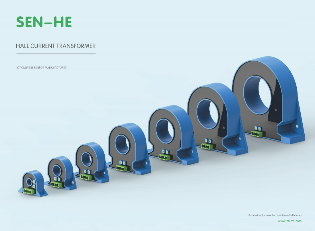
For years, Hall-effect sensors carried a quiet caveat: they drifted. Temperature swings and aging silicon would nudge the zero-point away from true, forcing designers to add periodic recalibration or accept creeping errors in their measurements. That limitation quietly shaped design choices across motor control, current sensing, and position feedback.
The turning point came when newer architectures stopped treating drift as an unavoidable cost. By integrating chopper stabilization with on-chip digital correction, manufacturers pushed offset drift down to a few milligauss per degree Celsius. Some designs now hold total error under 1% across the full industrial temperature range without external trimming. The sensor no longer needs a “warm-up” period or frequent field zeroing—it simply reads true from the first sample.
This changes what engineers can assume. A current sensor that stays put over years means fewer service calls and tighter control loops. A position sensor that doesn't wander with heat lets automotive and robotics teams drop redundant calibration routines. Drift hasn't disappeared as a physical phenomenon, but it has stopped being a design constraint. Hall-effect sensing finally delivers the stability its simplicity always promised.
Core Materials and Signal Conditioning: An Unseen Precision Path
The quiet backbone of any high-performance sensor system rarely gets the attention it deserves. Core materials—whether ferrite, permalloy, or nanocrystalline alloys—define how a signal is born, shaped, and delivered. Their magnetic permeability, saturation flux density, and thermal stability quietly determine whether a tiny current fluctuation becomes a clean, usable voltage or gets lost in noise. This is not the glamorous side of electronics; it is the patient, almost obsessive tuning of material grain structures and winding geometries that separates a mediocre transducer from a trustworthy one.
Signal conditioning walks hand in hand with these material choices, yet it often operates in the shadows. A carefully chosen core can reduce common-mode interference before it ever reaches an amplifier, but without proper filtering, impedance matching, or excitation control, even the best core will underperform. The real precision path emerges when designers stop treating core selection and conditioning circuitry as separate tasks. Instead, they iterate: a slight change in core air gap shifts the inductance, which then requires a different feedback capacitor to keep the phase margin stable. This loop of physical and electrical adjustments is where true linearity and repeatability are born.
What makes this path “unseen” is that it operates below the level of datasheet headlines. Nobody markets a sensor for its carefully annealed core or its second-order low-pass filter tuned to a specific flux density. Yet experienced engineers know that a drift of 0.02% over temperature is not luck—it is the residue of dozens of small decisions about core lamination thickness, shielding layout, and reference voltage stability. The next time a measurement system works flawlessly for years, remember that the real story is buried in the materials and the conditioning, not in the display or the connector.
Real Power Systems Need More Than a Spec Sheet Number
A bench test number tells you almost nothing about what happens when the load steps from ten percent to ninety percent in half a millisecond. Real power systems live in the messy territory of inductive kickbacks, cable inductance, and shared return paths. The voltage you measured on an open bench will sag, ring, or overshoot once it meets actual wiring and a bank of motors or actuators.
Thermal behavior is another place where a single figure falls apart. That headline wattage might be achievable for thirty seconds on a cold plate, but sustained operation inside a sealed enclosure at 45°C ambient is a different story. Components derate, electrolytic capacitors age faster, and protective circuits start tripping earlier than the datasheet implies.
What rarely shows up in a datasheet is how the system behaves when it is not alone. Generators, battery strings, and grid-tied inverters do not politely share load based on their nameplate ratings. They interact through droop settings, fault clearing times, and control loop phase margins. A real installation succeeds or fails on those interactions, not on a static number printed next to a logo.
Holding Accuracy Across Temperature and Time
Precision instruments often struggle when ambient conditions shift. A sensor calibrated at room temperature can drift noticeably once the environment warms or cools, and this error compounds over weeks of continuous operation. Holding accuracy across temperature and time means designing systems that resist these slow, silent changes rather than simply correcting them after the fact.
One practical approach combines low-drift reference components with active thermal stabilization. Instead of relying on a single factory calibration, the device continuously monitors its own temperature and adjusts internal gain or offset in real time. Materials with matched expansion coefficients prevent mechanical stress from pulling sensitive elements out of alignment. The result is a measurement chain that behaves the same on day one as it does after six months in a fluctuating climate.
For industrial monitoring and embedded control, this level of stability reduces the need for frequent recalibration and lowers the risk of false alarms. A pressure transmitter installed outdoors, for example, can hold its specified tolerance from a cold winter morning to a hot summer afternoon without intervention. That kind of repeatability isn’t just a specification on paper—it’s what keeps automated processes running safely with minimal human oversight.
A Different Benchmark for High-Voltage Current Sensing
Most published benchmarks for current sensors lean on laboratory conditions that barely resemble a high-voltage rail. Gain error, offset drift, and bandwidth are usually swept with the common-mode voltage held near zero, which tells you almost nothing about behavior at 800 V or 1.5 kV. In a real inverter or DC fast charger, the largest errors often come from electric field coupling into the isolation path, surface leakage across the package, and board-level contamination that accelerates under high dV/dt. A different benchmark has to measure those effects directly.
The alternative yardstick starts with transient common-mode rejection at switching edges above 50 kV/µs, then adds partial discharge inception voltage, creepage/clearance derating with humidity, and offset shift after repeated thermal cycles from cold soak to full load. It also looks at how the sensor behaves after 1,000 hours of DC bias at maximum working voltage, because isolation materials can drift in ways that a two-minute datasheet test never exposes.
This approach treats the sensing element as part of the insulation system rather than a standalone amplifier. For engineers designing solar string inverters, traction drives, or grid battery converters, this benchmark predicts field returns and certification failures far better than a clean sine-wave accuracy plot. It is less convenient to run, but that is exactly why it separates parts that survive high-voltage life from parts that only shine in a demo.
FAQ
Rather than relying on a basic Hall plate, the design pairs a proprietary magnetic core with digital signal processing that compensates for temperature drift and nonlinearity in real time. The result is a measurement chain that stays accurate even when the ambient temperature swings from -40°C to 150°C.
The sensing element uses an integrated chopper stabilization loop that cancels the DC offset and low-frequency flicker noise before the signal reaches the ADC. After conversion, a digital filter removes residual switching spikes, so the output remains clean enough for motor control loops that sample at high speed.
Battery management systems in electric vehicles, solar inverters, industrial servo drives, and precision power supplies are the main adopters. In each case, the ability to measure both small standby currents and large surge currents without changing the sensor range gives designers more headroom.
Yes. Because the Hall element responds to the magnetic field generated by the conductor, it naturally captures DC and AC components. The internal signal conditioning preserves the waveform shape, making the sensor suitable for true RMS monitoring as well as instantaneous current control.
After board-level calibration, typical total error stays below 0.5 percent across the full operating temperature range. Even without per-unit calibration, the factory-trimmed parts usually keep the error under 1 percent, which is a substantial improvement over standard open-loop Hall sensors.
The sensor die and magnetic core are encapsulated in a stress-isolating package, and the lead frame is designed to minimize mechanical strain transfer. For automotive and industrial use, optional conformal coating and integrated shielding protect against dust, moisture, and external magnetic fields.
The engineering team had seen too many field failures caused by thermal drift in shunt-based systems and saturation in current transformers. They set out to combine the isolation and non-invasive convenience of Hall sensing with the precision and stability normally reserved for laboratory-grade current probes.
Designers can choose from surface-mount variants with an internal current-carrying conductor for low-power rails, or larger modules with a through-hole aperture for high-current bus bars. Digital versions offer I2C or SPI interfaces with programmable alert thresholds, while analog versions provide a ratiometric voltage or current loop output.
Conclusion
Achieving microampere-level precision in a Hall-effect sensor rarely comes from a single breakthrough. It hinges on quieter decisions: selecting core materials that resist saturation and hysteresis, pairing them with signal conditioning that suppresses offset and noise without adding latency, and designing the magnetic path so that stray fields do not masquerade as current. This sensor company treats those choices as the product itself. The result is a Hall-effect platform that no longer trades drift performance for galvanic isolation. Instead of relying on a factory calibration that degrades the moment the device leaves the bench, the architecture keeps the zero point stable across load steps and recovers from inrush transients without operator intervention.
Field behavior in real power systems quickly separates a spec-sheet number from a trustworthy measurement. This company validates accuracy not in a quiet lab alone but under common converter stresses: high dv/dt, partial discharge, uneven thermal gradients, and busbar proximity effects. Temperature coefficients are specified across the entire operating range, and long-term drift is characterized rather than assumed away. For high-voltage current sensing, the benchmark shifts from percentage error at room temperature to repeatability after thermal cycling and moisture exposure. The company's approach makes those unseen variables part of the acceptance test, giving system designers a current sensor that holds its calibration where it matters.
Contact Us
Contact Person: Liu Mengyang
Email: [email protected]
Tel/WhatsApp: 8618727589233
Website: https://www.cnlrm.com/en/